Bookmark this site Online message 中文站Welcome to the official website of Beijing Yuanlai Water Treatment Equipment Co., LTD.!
Service Hotline
+86 010 59792055 / +86 13910114728

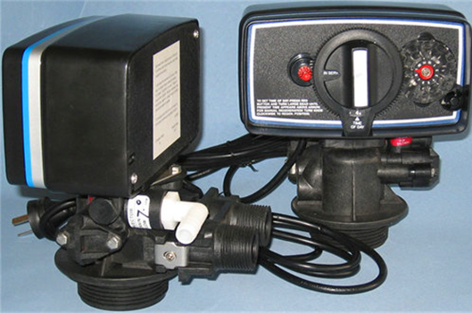
The specific features of Fleck control valves are as follows:
1,5600,5600SE,5000This type of control valve is suitable for small-scale civil water softeners, activated carbon filters for reverse osmosis pretreatment, and sand filters.
※Performance features
a.The pistons are arranged longitudinally
b.The valve body material is all engineering valve body material plastic
c.During regeneration, there is a hard water bypass, and an additional valve is needed to block the hard water bypass
d.5600Type regeneration includes6It has an additional backwashing step compared to other valves, making its regeneration quality superior to that of other valves
e.5000The backwash flow rate of the type control valve can reach17gpm .
Iii.5600Type installation and startup program
The installation of the water softener should be carried out in accordance with the inlet, outlet and sewage connection pipes recommended by the manufacturer, and should comply with relevant pipeline specifications.
1. Manually turn the control valve of the water softener to the working position to allow water to flow into the resin tank. When the water flow stops, open the inlet and outlet until all the air in the pipeline is discharged, and then close the inlet and outlet.
Note: You can manually rotate the knob at the front of the control valve to set it to different regeneration positions until the water softener is displayed at the desired position.
2. Manually turn the control valve to the backwash position to allow water to flow out through the drain outlet3or4Minutes.
3. Remove the rear cover plate of the control valve.
4. Make sure the amount of salt used is set as recommended by the manufacturer. If necessary, set the amount of salt according to the setting manual. Manually turn the control valve to the brine refilling position to fill the top of the air check valve with water.
5. Manually turn the control valve to the brine suction position to draw water from the brine tank until it stops.
6. Connect the power supply and observe the sight hole on the back of the motor to see if it is running. The regeneration date can be set by sliding the thin sheet on the jump wheel outward to expose its upper end. Each thin slice represents a day. The thin sheet at the red pointer represents the day. When the red pointer is turned clockwise, the thin sheet can be pulled out or pulled back to obtain the required regeneration time arrangement.
7. Manually push the beginning of the salt water refilling position of the control valve forward to allow the control valve to automatically return to the working position.
8. Add salt to the brine tank.
9. Install the control valve rear cover.
10. Make sure the bypass valve is in the normal working position.
Four5600 & 5600 typeECONOMINDER®Flowchart
1 Work location
Hard water enters the control valve from the inlet, passes through the lower piston groove and channel, and enters the tank from the top. Then, it flows downward through the resin layer to become purified water, and is discharged from the outlet of the upper valve through the return pipe of the lower distributor.
2 Pre-cleaning position
5 Minutes
Hard water enters the control valve from the inlet, passes through the lower piston groove, enters the tank from the top, then flows down through the resin layer, returns upward along the pipe through the lower water distributor, and is discharged through the piston hole and the drain port of the top piston groove.
5600 & 5600typeECONOMINDER®Flowchart (Continued
3 Backwash position
10 Minutes
Hard water enters the control valve from the inlet, passes through the lower piston groove and the piston ring bank, then flows down through the pipe and the lower water distributor into the tank, and then rises through the resin layer, the control valve flow channel, and the top piston groove, and is discharged from the sewage outlet.
4 Salt absorption position 50Minute fixed cycle section
Hard water enters the control valve from the inlet, passes through the lower piston groove, and flows through the nozzle of the jet injector to generate negative pressure, thereby drawing brine from the salt tank. The brine flows downward through the resin layer, passes through the lower distributor, ascends along the pipe, returns to the piston hole, and is discharged from the sewage outlet.
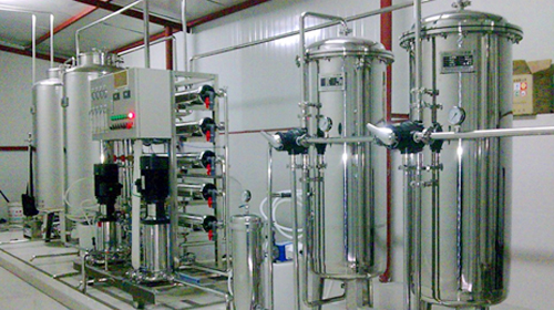
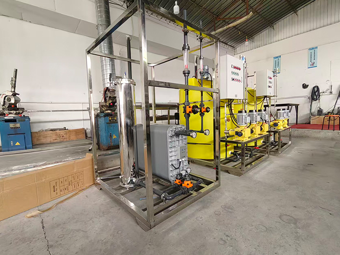
The requirements for water quality in industrial production are getting higher and higher. Ordinary tap water or well water contains impurities such as sediment, suspended solids, calcium and magnesium ions, heavy metals, and organic matter. Direct use will cause equipment scaling and corrosion, unstable product quality, increased energy consumption, and higher failure rates. Therefore, reverse osmosis pure water equipment has become an ideal choice for modern industrial water treatment.











 Landline:+86 010 59792055
Landline:+86 010 63780188
 Mobile:+86 13910114728
 Email:bjyuanlai@163.com
 Email:Wanda Plaza, Fengke Road, Fengtai District, BeijingBseat6Courtyard No.3Building No.7layer708
Yuanlai Homepage Softened water equipment Reverse osmosis pure water equipment Water supply equipment Engineering case Technical service Enter Yuanlai Site map
Softened water equipment Reverse osmosis pure water equipment Water purification equipment Water supply equipment Automatic dosing equipment High-purity water (ultra-pure water) equipment Wholesale of water treatment accessories
Electric power industry Petrochemical industry The electronic semiconductor industry The photovoltaic new energy industry Pharmaceuticals & Biochemical Engineering School research units Food and beverage industry Enterprises and public institutions
Reverse osmosis membrane Star-counting pump Fleck Valve Runxin Valve Instruments and meters Ultrafiltration membrane Softening resin Resin tank
Telephone consultation
"Online message
Wechat consultation