Bookmark this site Online message 中文站Welcome to the official website of Beijing Yuanlai Water Treatment Equipment Co., LTD.!
Service Hotline
+86 010 59792055 / +86 13910114728

FleckFleck2150Instruction Manual for Time and Flow Type Control Valves
FleckFleck2150Mechanical flow control regenerative type Setting of traffic flow Flow control panel * 24 HOUR GEARIn a standard instant regeneration system, there is none24 HOUR GEARThe set flow rate is obtained by calculating the periodic water production volume based on the exchange capacity of the resin filled in the resin tank and subtracting the necessary reserve volume. Pull out the flowmeter and rotate it to align the set flow rate with the white dot on the flowmeter. Then release the flowmeter and make sure the gears mesh well.
Note: After the initial installation of the flowmeter, an inspection should be carried out
1, Turn the manual regeneration valve and go through the procedure once.
2, Turn the program wheel clockwise or rotate it clockwise Rotate the wheel to align the set flow rate with the small white point.
3, The set traffic can be changed at any time. Time setting*Only refers to systems with delay function Press the red button and release it24The meshing of the hour dial. Turn the time disk to align the actual time of the day with the words"time of dayThe arrow of ". Release the red button to reengage with the time dial. How to regenerate manually Turn the manual regeneration knob clockwiseMANUAL REGENERATION KNOBWhen a "click" sound is heard, it marks the beginning of the regeneration process. It takes approximately one full rotation of the manual regeneration knob3In hours, one full turn of the knob completes one regeneration process. Start regeneration immediately When the flow disk rotates to the quantity you have set, the timer starts the regeneration program.
FleckFleck2150, 2750,2850,2900,3150,3900System workflow
1 Work location Hard water enters the control valve from the inlet, passes through the lower piston groove and channel, and enters the tank from the top. Then, it flows downward through the resin layer to become purified water, and is discharged from the outlet of the upper valve through the return pipe of the lower distributor.
2 Backwash position Hard water enters the control valve from the inlet, passes through the lower piston groove and the piston ring bank, then flows down through the pipe and the lower water distributor into the tank, and then rises through the resin layer, the control valve flow channel, and the top piston groove, and is discharged from the sewage outlet. The purpose of backwashing is to loosen the resin bed and clean impurities adsorbed on the surface, etc.
3 Salt absorption position Hard water enters the control valve from the inlet, passes through the lower piston groove, and flows through the nozzle of the jet injector to generate negative pressure, thereby drawing brine from the salt tank. The brine flows downward through the resin layer, passes through the lower distributor, ascends along the pipe, returns to the piston hole, and is discharged from the sewage outlet.
4 Slow cleaning position After all the brine has been sucked up, the hard water continues to enter the control valve from the inlet, passes through the lower piston groove, flows through the nozzle, passes down through the resin layer, enters the pipe from the lower water distributor, rises into the piston hole, and then flows out from the drain port.
5 Quick cleaning position Hard water enters the control valve from the inlet, passes through the lower piston groove and the piston ring bank, then flows down through the pipe and the lower water distributor into the tank, and then rises through the resin layer, the control valve flow channel, and the top piston groove, and is discharged from the sewage outlet.
6 The position for refilling water in the salt tank Hard water enters the control valve from the inlet. Some of the hard water flows into the salt tank through the lower piston groove, the throat of the jet injector, the salt suction valve and the salt suction flow-limiting gasket. Its fully hard water passes through the top of the lower piston tank, descends through the resin layer, turns into purified water, enters the lower distributor, ascends along the pipe, and is discharged from the valve body outlet. Note: The salt tank will automatically replenish water, so the amount of salt in the salt tank should always be maintained at a level sufficient to meet the needs of the next regeneration process.
1, Soft water should be installed on a solid and level surface, and drainage pipes should be designed nearby.
2, The salt tank should be placed close to the resin tank. To increase the salt absorption rate, the length of the salt absorption pipe should be shortened as much as possible.
3, Filling quartz sand: Before filling, the pipe should be placed in the resin tank (at this time, the sealing tape at the top of the pipe should not be opened to prevent sand, gravel and resin from entering the lifting pipe), then the quartz sand should be placed in and the sand layer should be evenly spread at the bottom of the tank.
4, Filling resin: Pour the treated resin into the resin tank according to the approved filling quantity.
5, Remove the tape from the pipe, align the upper end of the pipe with the socket at the bottom of the control valve, and carefully rotate the control valve clockwise (Note: During the installation of the control valve, make sure the pipe is inserted into the valve body). Then, secure the control valve firmly to the tank.
6, Connect the pipes and power supply as shown in the installation schematic diagram.
7, When starting the water softener, the bypass valve should be closed first, then the outlet control valve should be opened, and finally the inlet control valve should be slowly opened (Note: If the inlet control valve is opened too quickly, the water and residual air in the pipeline will enter the water softener, causing the resin to flow out of the resin tank with the water flow).
8, Set the time and program controller according to the methods described in the manual. During the initial usage stage, it is necessary to enhance water quality monitoring and adjust the restoration program according to water quality changes to keep it in the best working condition.
9, There should be sufficient regenerant in the tank to ensure the amount of salt needed for the next cycle of regeneration.
10After the above installation and commissioning, samples will be taken for testing. Water supply can be provided once the water quality meets the requirements.
FleckFleck2150Mechanical time-controlled regenerative type How to set the regeneration date Time control panel Turn the date wheel to make the digital"1Align with each small protrusion on the edge of the date wheel Represent a day. The rotation of the date wheel relies on24Driven by the hour clock, the clock rotates Every week, a protrusion is broadcast, and the date wheel is rotated by a digital one.1"Switch to digital2" day The wheel can be pulled out outward, and the stainless steel plate determines the regeneration date. Which number corresponds? The day when the stainless steel sheet is pulled out is the regeneration date. How to set the time Press the red button and release it24The meshing of the hour dial, rotate the time dial red until"time of dayAlign the arrow with the actual time of the day, release the red button, and restore the engagement with the time dial.
How to regenerate manually
Turn the manual regeneration knob clockwiseMANUAL REGENERATION KNOBWhen a "click" sound is heard, it marks the beginning of the regeneration process. It takes approximately one full rotation of the manual regeneration knob3In hours, one full turn of the knob completes one regeneration process. How to set the regeneration cycle program
The regeneration cycle program has been set at the factory3The regeneration process takes hours, but the time can be extended or shortened according to the different local conditions of the user. Timer Open the controller cover, then turn the time disk to the right to see the regeneration timer. To change the regeneration program,
Remove the timer. The method is to pinch the timer pin inward and pull it outward. Then the timer disk can be removed from the back of the control disk. How to change the length of backwashing time
A circle of numbers is marked on the edge of the timer.0-160), from0The initial group pin is used to control the backwashing time. For example: If the group has six pins, the backwashing time is12Minutes (One pin is.2Changing the number of pins in minutes is equivalent to changing the backwashing time accordingly. How to change the duration of salt absorption and slow washing
The number of pin holes between the group pins and the group pins on the timer controls the time of these two states, and each hole is equivalent to2In minutes, the number of holes increased or decreased will change the length of the brine absorption and slow washing time. When adjusting, increase or decrease the holes by moving the position of the group pins. How to change the length of the quick wash time The number of pins on the timer group controls the length of the quick wash time. For each additional or reduced pin, the quick wash time increases or decreases by two minutes. How to change the duration of filling the salt tank with water
The number of pins in the third group on the timer is used to control the duration of water injection. Each hole is equivalent to2In minutes, when adjusting, increase or decrease the number of holes by moving the position of the third group of pins. The regeneration program terminates when an external microswitch comes into contact with the two pins at the end of the water injection pin hole. However, the timer will continue to rotate until a microswitch inside contacts the arm to rotate into the circular notch of the timer.
FleckFleck2150Product Overview
System technical parameters
Import pressure0.2 Mpa-0.6 Mpa
Operating temperature2 ℃-50℃
Effluent hardness≤0.03mmol/L
Power supply used:220v /50Hz AC
Layout form: Single tank or two tanks in parallel
Regeneration method: Co-current regeneration
Operation procedure: Automatic program control
Resin used001×7Strongly acidic cation exchange resin
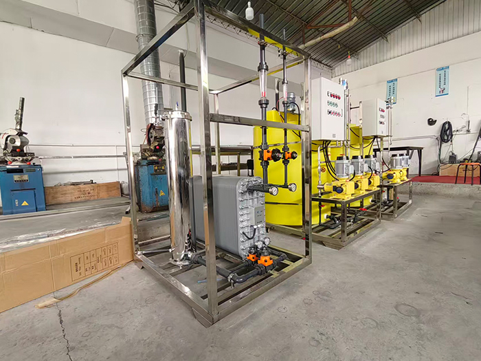
Yuan LaiEDIThe ultra-pure water equipment uses electro-deionization technology.EDIElectrodeionization is a water purification method that combines the dual advantages of electrodialysis and ion exchange. It does not require acid-base chemical regeneration and can continuously and stably prepare high-purity ultrapure water. Under the action of a direct current electric field, ion separation in water is completed. At the same time, water is electrolyzed to generate hydrogen ions and hydroxide ions, achieving automatic regeneration of the resin without the need to stop the machine for manual regeneration. The pre-treatment combined with reverse osmosis can prevent oxidized substances from damaging the resin, ensuring stable effluent quality and widely meeting the high-standard water usage requirements of various industries.
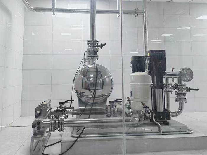
The non-negative pressure water supply equipment can be directly connected to the municipal water supply network, making full use of the residual pressure of the original network for superimposed water supply. Fully enclosed operation does not require the construction of a domestic water tank, eliminating secondary pollution. Intelligent variable frequency voltage stabilization, energy-saving, quiet and easy installation, it is the preferred equipment for secondary water supply in high-rise residential buildings and commercial buildings.
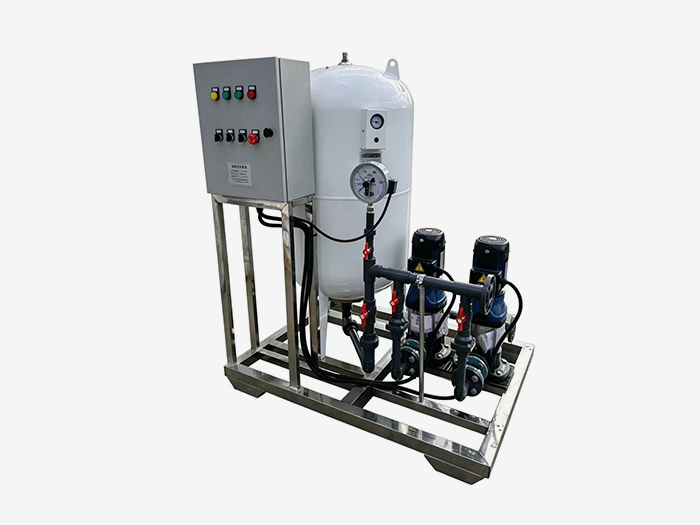
Constant pressure water supply equipment is widely used in central air conditioning, floor heating, industrial closed-loop water circulation, and boiler systems. It integrates automatic pressure stabilization, automatic water replenishment, automatic exhaust, pressure relief and buffering functions. It stabilizes the pressure in the pipeline network, eliminates abnormal sounds caused by air blockage, and prevents damage from negative pressure and water shortage in the pipeline. It is an essential supporting equipment for HVAC and circulating water systems.











 Landline:+86 010 59792055
Landline:+86 010 63780188
 Mobile:+86 13910114728
 Email:bjyuanlai@163.com
 Email:Wanda Plaza, Fengke Road, Fengtai District, BeijingBseat6Courtyard No.3Building No.7layer708
Yuanlai Homepage Softened water equipment Reverse osmosis pure water equipment Water supply equipment Engineering case Technical service Enter Yuanlai Site map
Softened water equipment Reverse osmosis pure water equipment Water purification equipment Water supply equipment Automatic dosing equipment High-purity water (ultra-pure water) equipment Wholesale of water treatment accessories
Electric power industry Petrochemical industry The electronic semiconductor industry The photovoltaic new energy industry Pharmaceuticals & Biochemical Engineering School research units Food and beverage industry Enterprises and public institutions
Reverse osmosis membrane Star-counting pump Fleck Valve Runxin Valve Instruments and meters Ultrafiltration membrane Softening resin Resin tank
