Bookmark this site Online message 中文站Welcome to the official website of Beijing Yuanlai Water Treatment Equipment Co., LTD.!
Service Hotline
+86 010 59792055 / +86 13910114728

Water quality requirements for ion exchangers
To prevent resin contamination, the quality of the raw water entering the ion exchanger for treatment should meet the requirements table3-39Requirements.
Strong base anion resins are prone to contamination by organic matter in the raw water and oxidation degradation products of cation exchange resins during operation. The degree of contamination of strong base anion resins by organic matter is related to the content and type of organic matter, as well as the ratio of organic matter to total anions in water. Does the water treatment system need measures to remove organic matter that can be adoptedAValue indicator
The oxygen consumption index is27℃,KMn04Act as an oxidizing agent to oxidize4hMeasuredO2Value.
A<0.004No measures to remove organic matter are required.
A=0. 004~0. 008Macroporous resin is used in the reclining system.
A=0. 008~0. 001 5Use activated carbon orC1Pretreatment of type resin.
A>0. 015Chlorination oxidation decomposition and activated carbon adsorption treatment were adopted.
For example, designing water qualityAfor
A="Oxygen consumption"Mg02 /L】/Total anion quantitymg/L】=0. 016 3>0. 015
Therefore, in addition to adding oxidants to the effluent from the clarifier, it is also necessary to add activated carbon adsorption treatment.
Ii. Softening of hard water
(one)Sodium ion exchange system
(a)The raw water and the effluent from the sodium ion exchanger are mixed in proportion, which is suitable for users with low requirements for hardness.
(b)When the hardness of the effluent from the primary sodium ion exchanger fails to meet the requirements, the primary sodium ion exchangers can be connected in series to form a secondary sodium ion exchange system. The first-stage sodium ion exchanger can be regenerated by either co-current or counter-current flow;The effluent quality of counter-current regeneration can reach the secondary effluent quality, so a secondary sodium ion exchanger is usually not set up. The height of the exchanger layer in the secondary sodium ion exchanger is1. 2~1. 5mLeft and right, the flow velocity is less than50m/hCo-current regeneration is adopted.
(two)Process data of sodium ion exchange system
Iii. Alkali Removal
For high alkalinity(If the alkalinity is greater than2mmol/L)The raw water, if only carried outNaWhen ion softening treatment is used as feed water for steam boilers, the following decomposition and hydrolysis reactions occur at high temperatures
2NaHC03==Na2C03 + CO2↑+H20
Na2 C03+H20=2NaOH+C02↑+H20
After the above reaction occurs, it will cause the boiler water to be freeOH-It increases and the total alkalinity rises. In steamCOZThe increase in concentration causes acid corrosion in the steam and condensate water systems as well as alkali corrosion in the boiler water system. The continuous blowdown rate of low-pressure boilers needs to be calculated based on the make-up water rate(The steam pressure is less than or equal to it2. 5MPaAt that time, the boiler blowdown rate should not be greater than10%Steam pressure is greater than2. 5 MPaAt that time, the boiler blowdown rate should not be greater than5%And check the relative alkalinity(NaOH/The dissolved solid form is not greater than0. 2)To prevent the caustic embrittlement of the boiler metal. After sodium ion exchange with acid, the increase of neutral salts in water helps maintain the relative alkalinity at no more thano.2It's beneficial. Therefore, for raw water with high hardness and high alkalinity, it is considered to combine softening and dealkalization treatment to improve the safety and economy of boiler operation.
The main water treatment methods for alkali removal include sodium ion exchange with acid system and parallel connectionH-NaIon exchange systems and series connectionH-NaIon exchange system. Regardless of which system is adopted, a sodium ion exchanger should be passed through after the system(Or "grade sodium ion exchanger.)WhenpHWhen the value is low, the sodium ion exchanger can act as a buffer to absorb a certain amount of the influent waterH+;whenpHWhen the value is too high, it will be releasedHTen The reaction situation in the sodium ion exchanger is as follows:
RNa+H2CO3→RH+NaHCO3
RH+NaHC03→RNa+H20 +CO2
The operating conditions of the ion exchange denitrification system are shown in the table3-41.
(one)Sodium ion exchange acid addition system
The sodium ion exchange acid addition system is shown in the figure3-29As shown, its reaction equation is
2NaHC03+H2 S04 = Na2S04 + 2 CO2↑+2H20
Control the required alkalinity by the amount of acid added, and generally keep the residual alkalinity greater than0. 5mmol/L.
When adding acid, sulfuric acid needs to be thoroughly mixed with soft water through a mixer. The free radicals produced after mixingCOZAccording to the reduction1mmol/LHC03Alkalinity generationCO2 44mg/LCalculate and remove through a decarbonizer. Corresponding to addition1mmol/LThe amount of solid dissolved by sulfuric acid increases49mg/L.
(two)Parallel sodium ion exchange system
H-NaParallel ion exchange systems are suitable for raw water with high alkalinity. The neutralization reaction of the effluent after hydrogen and sodium ion exchange of the raw water is
2NaHC03 + H2so4→Na2 S04+2H2O+2C02
NaHC03+HCl→NaCl+H20+CO2
It is produced by neutralizing and mixing raw waterCO2It can be removed by a decarbonizer. To ensure that no mixed water is produced after neutralization, the water after neutralization and mixing should maintain a certain residual alkalinity, and the proportion of water entering the hydrogen and sodium ion exchange should be maintained at a certain level.
(three)Series hydrogen-sodium ion exchange system
1.Strong acid hydrogen - sodium ion exchange system
The raw water is divided into two parts, and one part is introducedHThe switch, another part bypasses andHThe water from the exchanger is mixed to makeHThe acidity in the effluent from the exchanger undergoes a neutralization reaction with the alkalinity in another portion of the raw water, resulting in the product after the reactionCO2The water is removed by a decarbonizer and then enters a water tank where it is pumpedNaSwitch. The carbon remover should be installed atNaBefore the exchanger, otherwise if it containsCqThe water passes through firstNaThe exchanger will produce reactions such as:RNa+H2C03→RH+NaHC03Then the height of the water pendant increased inside.
2.Weak acid hydrogen-sodium ion exchange system
Weak acidHCation resin has a large working exchange capacity and is weak acidHWhen regenerating the type of resin, it is only the theoretical amount1.1The waste liquid discharged during the regeneration of weakly acidic resinpHThe value is close to neutral, which is conducive to the treatment of acidic wastewater. Weak acidH-NaThe main technical parameters of the ion exchange system are shown in the table3-42"Table"3-43.
Based on operational experience, when the ratio of carbonate hardness to total hardness in the influent water is0.5~1The total hardness is greater than2mmol/LWhen in use, weak acids should be adoptedH--NaThe type of ion exchange system can achieve better economic benefits.
The raw water is divided into two parts. One part of the raw water is treated with weak acidHIn the type of exchanger, another part of the raw water is directly mixed with the effluent, and the reaction is producedCO2It is removed by the carbon remover. If the alkalinity is too low, it can be adjusted by adding raw water. The degassed water is pumped into the sodium ion exchanger through the water tank by a pump, and then the non-carbonate hardness is removed. After the effluent meets the standards, it enters the water tank and is sent to the boiler.
Iv. Desalination System
(one)Common combinations of desalination systems
(two)Primary desalination system
A typical primary desalination system(Also known as a double-bed or two-bed three-tower system)It is composed of a strong acid cation exchanger, a decarbonizer and a strong base anion exchanger. Unit-based primary desalination salt system(Series system)It is composed of one cation bed, one decarbonizer and one anion bed connected in series to form a group. During the operation of ion exchange desalination, whether the cation bed or the anion bed fails first, they are regenerated simultaneously;The main control primary desalination system(Parallel system)That is, the inlet and outlet water pipes of multiple male and female beds are respectively connected to the main water pipe and operate in parallel, among which the carbon remover is shared(It cannot be less than2Taiwan)Each exchanger is regenerated after failure respectively. The unit system and the master control system are shown in the figure3-33.
1.The changes in water quality during the operation of the primary desalination system
(1)Strong acid anode exchanger(Yang bed)Work characteristics. The function of the anode bed is to remove waterH+All cations other than ions. When the cation bed is in operation, water flows from top to bottom through strongly acidic waterHThe type of resin layer, due to the different selectivity of the resin layer for various cations, the ions adsorbed form stratification within the resin layer. During operation,Ca+,Mg2+,Na+The height of the three resin layers will continuously expand downward. When the sodium ion concentration in the effluent during operation increases, the resin will fail and must be regenerated until it fails. In fact, the interfaces between each layer are not very distinct, and there are varying degrees of layer mixing phenomena occurring.
figure3-34The following shows the effluent characteristics of the cation bed after regeneration and operation. When the cation bed is regenerated and then flushed, the content of various impurities in the effluent drops rapidly, and the effluent quality reaches a certain standard(If the sodium content is not greater than100μg/L)At that time, it can be put into operation, and the water quality will remain basically stable thereafter. When running to a certain extent, as shown in the figure3-34In thebAt this point, the sodium leakage increases, the acidity decreases, and the resin enters a state of failure. When the sodium content in the effluent from the cation bed exceeds the control index(If the sodium content reaches500ilg/L)It indicates that the anode bed has failed and should be stopped from operation.
(2)Strong base anion exchanger("Yin bed")Work characteristics. It is strongly alkaline in YinqingOHType exchange resin can be removed from waterOHWhen various anions other than one ion are exchanged, due to the different selectivity of the resin for ions, the ions that are adsorbed during the operation of the anion bed will also stratify.
The effluent characteristics of the anion bed when the anion bed has not failed
When the operating water flow reachesbAt the o 'clockSi02The content increasespHWhen the value drops, the conductance first slightly decreases and then rises again. The change in electrical conductivity is due to waterH+andOH-To compare·Other ions are conductive. When the total content of these two ions in the effluent is very small, one of them has a lower conductivity((bpoint). inbBefore the hour, due toOHThe higher the content, the greater the electrical conductivity of water;inbAfter clicking, due toHAn increase in the content of ten leads to an increase in the electrical conductivity of water.
The effluent characteristics of the anion bed when the anion bed fails
When the operating water flow reachesbAfter the point is set, when the cation bed fails, the amount of sodium leakage increases. These sodium ions pass through the anion bed and are converted into sodium hydroxide, causing water to flow out of the anion bedpHThe value, conductivity and sodium content all increased. At the same time, because water is passing through strong alkalinityOHWhen the alkalinity of the type exchange resin increases, the exchanger cannot absorb silicon in the water, resulting in an increase in the silicon content in the effluent. Continuously measure the effluent from the anion bedpHThe value can distinguish whether it is the failure of the positive bed or the negative bed. For example, if the negative bed fails, it can still be usedSi02The content and electrical conductivity are used for supervision and judgment.
When the anion bed is in operation, water usually comes outpHThe value is7~9Between them, the silicon content is less thanSi02"Calculate, less than"0. 1mg/LThe electrical conductivity is2-5μS/cm (25℃)(Adopt countercurrent regeneration). Since the anion bed is located behind the cation bed, the effluent quality of the anion bed is greatly affected by that of the cation bed.
2.The selection of series or parallel chemical desalination systems
(three)Secondary desalination system
1.Overview
A primary mixed bed is connected in series after the primary desalination system(A combination of strong acid cation resin and strong base anion resin)It is called a secondary desalination system. oneILT7-WWhen the desalination system is in operation in series with a mixed bed, the salt content entering the mixed bed can be adjusted according to20mg/LConsidering that the working exchange capacity of the strong acid cation and anion resins and the strong base anion resins in the mixed bed can be roughly the same as that of the cation and anion resins80%Selection. The periodic water production capacity of each mixed bed can also be determined based on the total volume of strong acid cation resin and strong base anion resin in the mixed bed8000~10 000Double estimation. General effluentpHThe value is6.8~7.0Between them, the silicon content is less thansiO2"Calculate, less than"0. 02mg/LThe electrical conductivity is0.1~0.5μS/cm(25℃)
2.Selection of equipment for secondary desalination systems
A column of outputQ=150m3/hSelection of main equipment for the unitized two-stage disk removal system
【 Coagulation - Clarification - Filtration System for Clear Water→Strong acid cation exchanger→Carbon dioxide remover→Middle water tank→Strong base anion exchanger→Mixed bed→【 Deionized water Tank
(1)Raw water quality analysis data(See table3-47). pHfor8. 1; Si02for11.2mg/L (11.2/60=0.186mmo1/L);The suspended matter is300m1/L.
(2)Equipment selection
1Mixed eight beds
A.Determine the specifications of the mixed bed equipment(See table3-48)
B.Determine the height of the resin layer(Anion resin volume:Cationic resin volume=2:1)See the table3-49.
2)Anion exchanger(Counter-current regeneration without top pressure)Process data calculation.
3)Calculation of carbon dioxide remover and fan(See Section 3 of Chapter 7, Carbon Remover).
A.The original data required for the carbon remover.
B.Calculate the required area for the decarbonizerF"Diameter"Do.
4)The volume of the middle water tank. The effective volume of the intermediate water tank should be sufficient for the output of each set of water treatment equipment in a unitized system2~5minThe water storage capacity should not be less than2m3(The main control system should be capable of providing power for the water treatment equipment15~ 30minWater storage capacity). Take the volume of the middle water tank15m3.
5)Cation exchanger(Counter-current regeneration without top pressure)Process data calculation(See table3-53).
(four)The operating status of weak type resins
1.Weak acid cation exchange resin
The selection sequence of various metal ions in water by weak acid cation exchange resin is as followsCa2+ > Mg2+ > Na+And, as forH+The affinity of ions is greater than that of any other ions. From the picture3-37It can be seen from the above that when the weak acid cation exchange resin is in operation, if the temporary hardness leakage value exceeds the temporary hardness of the raw water50%In the future, the increase in its working exchange capacity will be very slow, and the practical value of further increasing the leakage degree to enhance its exchange capacity is not significant.
2.Weak base anion resin
It is generally believed that weak base anion resins can only absorb strong acids and react with strong acid anions in water under acidic conditionsSO2-4,NO-3,CI-Make an exchange. Weak base anion resins contain a small amount of strong base groups. At the beginning of operation, while attracting strong acid anions, they also attract some weak acid anions. However, it is quickly displaced by the strong acid anions in the influent water, with a very small residual amount. In the initial stage of operation, it can absorb some weak acid anionsHC03,HSiO-3Average in the periodic effluentSiO2andCO2The concentration is basically equal to that of the influent. From the picture3-38It can be seen from the above that during operation, when the weak base resin is close to failure, the strong acid anions start to leak through, the effluent becomes acidic, and the electrical conductivity rises rapidly. It can also be seen from the picture0From then on, the leakage of strong acid from the general control weak base resin layer is zero.
(five)Combined equipment for strong and weak type resins
1.The proportion of strong and weak cationic resins
2.The proportion of strong and weak anion resins
3.The proportion of strong and weak resins and the bed type should be determined based on the process parameters and applicable water quality
When the height of the weak acid resin layer is0. 6m,The total height of the coconut layer is2. 0mwhen(That is, the volume of the weak acid resin layer is the total volume30%)The average working exchange capacity of the combined application process of cation and resin is significantly higher than that of a single bed.
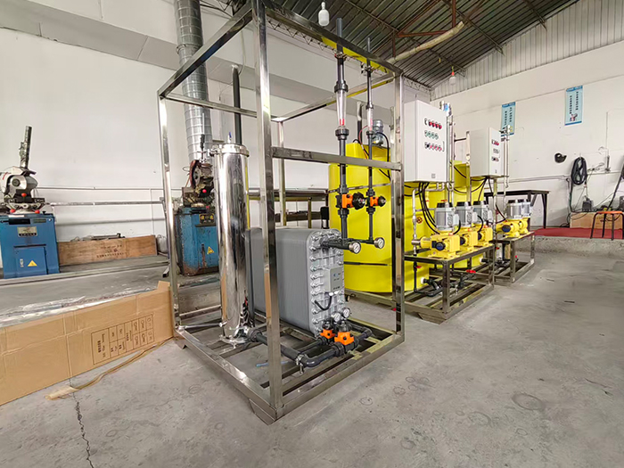
Yuan LaiEDIThe ultra-pure water equipment uses electro-deionization technology.EDIElectrodeionization is a water purification method that combines the dual advantages of electrodialysis and ion exchange. It does not require acid-base chemical regeneration and can continuously and stably prepare high-purity ultrapure water. Under the action of a direct current electric field, ion separation in water is completed. At the same time, water is electrolyzed to generate hydrogen ions and hydroxide ions, achieving automatic regeneration of the resin without the need to stop the machine for manual regeneration. The pre-treatment combined with reverse osmosis can prevent oxidized substances from damaging the resin, ensuring stable effluent quality and widely meeting the high-standard water usage requirements of various industries.
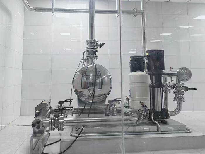
The non-negative pressure water supply equipment can be directly connected to the municipal water supply network, making full use of the residual pressure of the original network for superimposed water supply. Fully enclosed operation does not require the construction of a domestic water tank, eliminating secondary pollution. Intelligent variable frequency voltage stabilization, energy-saving, quiet and easy installation, it is the preferred equipment for secondary water supply in high-rise residential buildings and commercial buildings.
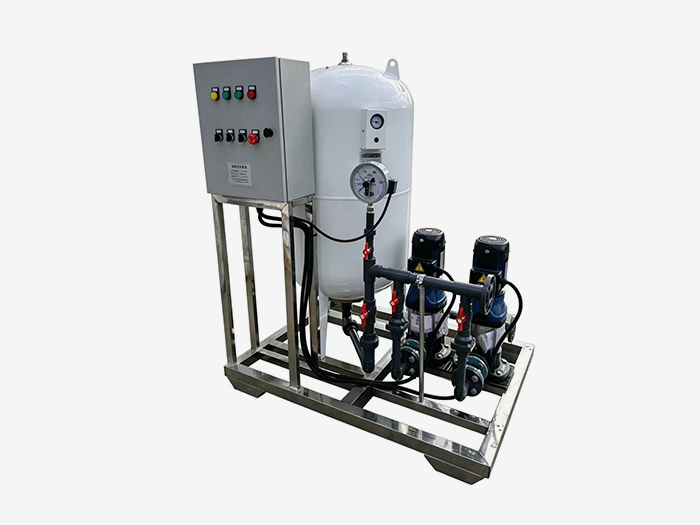
Constant pressure water supply equipment is widely used in central air conditioning, floor heating, industrial closed-loop water circulation, and boiler systems. It integrates automatic pressure stabilization, automatic water replenishment, automatic exhaust, pressure relief and buffering functions. It stabilizes the pressure in the pipeline network, eliminates abnormal sounds caused by air blockage, and prevents damage from negative pressure and water shortage in the pipeline. It is an essential supporting equipment for HVAC and circulating water systems.












 Landline:+86 010 59792055
Landline:+86 010 63780188
 Mobile:+86 13910114728
 Email:bjyuanlai@163.com
 Email:Wanda Plaza, Fengke Road, Fengtai District, BeijingBseat6Courtyard No.3Building No.7layer708
Yuanlai Homepage Softened water equipment Reverse osmosis pure water equipment Water supply equipment Engineering case Technical service Enter Yuanlai Site map
Softened water equipment Reverse osmosis pure water equipment Water purification equipment Water supply equipment Automatic dosing equipment High-purity water (ultra-pure water) equipment Wholesale of water treatment accessories
Electric power industry Petrochemical industry The electronic semiconductor industry The photovoltaic new energy industry Pharmaceuticals & Biochemical Engineering School research units Food and beverage industry Enterprises and public institutions
Reverse osmosis membrane Star-counting pump Fleck Valve Runxin Valve Instruments and meters Ultrafiltration membrane Softening resin Resin tank
