Bookmark this site Online message 中文站Welcome to the official website of Beijing Yuanlai Water Treatment Equipment Co., LTD.!
Service Hotline
+86 010 59792055 / +86 13910114728


How to use the boiler water softening equipment and debug and install it
Installation
1General requirements for installation
①The inlet water pressure should be within0.2-0.5MPaWhen the water source pressure fails to meet the requirements, a booster pump can be installed to increase the inlet water pressure. If the pressure is too high, a pressure reducing valve should be installed to control the inlet water pressure.
②The inlet water temperature should be within5-45℃Between them, the power supply adopts alternating current200V/50Hz.
③The water softener should be installed on a solid platform with unobstructed drainage nearby and sufficient space for operation and maintenance.
④The working environment temperature should be within5-50℃Between them, relative humidity≤95%(5℃At that time.
2Installation of control valves and resin filling (top-mounted form)
Step: First, firmly install the lower water distributor at the bottom of the pipe, then insert it into the resin tank, with the upper end of the pipe lower than the tank opening0.5mmCut off the section and guide the Angle, then seal the pipe opening with tape to prevent resin from leaking in.
Step: Pour the quartz sand along the gaps around the pipe into the resin tank and make it level at the bottom of the tank. The quartz sand should be higher than the lower water distributor20mmQuartz sand should be laid in layers according to particle size grades, mainly to serve the purpose of water distribution (for diameters less than.500mmResin tanks are generally not filled with quartz sand.
Step 3: Evenly fill the resin into the resin tank. After reaching the specified layer height, inject it10%Immerse the resin in a salt solution until it is fully expanded.
After the resin is filled, the sealing tape of the tube should be removed. During the above operation, it is necessary to ensure that the tube is always kept at the position of the resin tank opening.
Step 4: Install the upper water distributor onto the control valve, then insert the pipe from the upper water distributor into the control valve. Carefully rotate the control valve clockwise and tighten it directly onto the interface of the resin tank (or fix it with a flange connection).
Pay attention to the tightness of the upper water distributor with the control valve and pipe, and the lower water distributor with the pipe to prevent the resin from escaping. The pipe and the control valve should be tightly sealed without leakage; otherwise, hard water will seep in.
3Requirements for pipe connection
①The pipes connected to the water softener should be made of water supply plastic pipes, and the drainage pipes must not be made of soft plastic pipes to prevent pipe deformation and affect the drainage effect.
②Connect the inlet and outlet water pipes according to the arrow marks on the control valve's inlet and outlet. Use a flow-type regenerative controller, and install the flowmeter at the outlet.
③The inlet and outlet pipes should be equipped with pressure gauges and manual valves. At the same time, a bypass valve should also be installed at the outlet
A sampling valve should also be installed before the water pipe valve. There is usually a device installed after the inlet pipe valve Y This type of filter prevents dirt in the pipeline from clogging the valve body and causing the equipment to fail to operate normally.
④The connection length of the drainage pipe should not exceed6mMinimize the degree of curvature and strictly prohibit the installation of valves.
⑤The connection length of the salt water pipeline should not exceed2mIt is essential to maintain good sealing; otherwise, it will affect the regeneration effect of the water softener.
4The equipment is supplied with water
When the resin is10%Soak in a salt solution18-20The equipment can be filled with water only after it has fully expanded for a certain period of time.
Step: First, close the inlet and outlet water valves, open the bypass valve to flush out the impurities in the pipeline, and then close the bypass valve.
Step: Confirm that the electrical parameters of the water softener are consistent with the power supply (Note:SEThe input voltage of the type regenerative controller is alternating current12V/50HzTherefore, input AC should be selected220V/50HzOutput AC12V/50HzThen connect the power supply to the transformer. Manually start the regeneration controller, adjust the control valve to the backwash state, and slowly open the water inlet valve 1/4 At this point, you can hear the sound of air being discharged from the drain pipe. After all the air has been discharged, fully open the water inlet valve to flush out some impurities in the resin until clear water is discharged through the drain pipe.
Step 3: Adjust the control valve to the forward wash position until the water output is qualified.
Step 4: Adjust the control valve to the water filling position of the salt tank, inject the designed water volume into the salt tank, then add solid granular salt, and the operation and debugging can be carried out.
Fleck The application of fully automatic control valves
Fulai Company possesses advanced technology in water treatment automatic control devices and its products are of stable quality. Therefore, Fulai's fully automatic control valves have become the preferred choice for fully automatic water softeners.
I.5600Control valve
1Introduction to Control valves
5600The control valve belongs to small civil control valves, with a single piston arranged longitudinally, and is suitable for single-valve and single-tank systems.5600The control valve is a hard water bypass valve. When it is used for soft water treatment in industrial boilers, a hard water blocking valve is installed at its water outlet. The hard water blocking valve generally adopts a normally open solenoid valve. It automatically closes the outlet pipeline during the regeneration of the water softener and opens the outlet pipeline during operation. The opening and closing of the solenoid valve is controlled by a microswitch added beside the saltwater CAM.
2Regenerative controller
5600The control valve regeneration controller adopts a mechanical type. It is controlled by a time motor for the working time of each step of the regeneration program and also serves as the power source for the driving device. Moreover, it only has a time type and a flow delay type (with a flowmeter installed at the water outlet), but no flow instantaneous type.
The regeneration controller has the regeneration time fixed at the factory2:30AMThat is when24Hour gear2:30AMWhen aligned with the time arrow, regeneration begins. Of course, regeneration can also be advanced or postponed as needed. Also, during a power outage24The hour gear also stopped moving, so the regeneration time was recalibrated after the power was cut off.
Regeneration time setting method: First, press the red time button on the left to make it24When the hour gear is loosened, it can be adjusted24The hour gear, until the current time aligns with the time arrow, then the regeneration time is set at2:30AM.
For example: The current time is10:00AMIf you don't want to change the regeneration time, just use24On the hour gear10AMAlign with the time arrow. If you want to postpone2Regeneration within hours should be used24On the hour gear8AMAlign with the time arrow if you want to move it forward2Regeneration within hours should be used24On the hour gear12AMAlign with the time arrow.
The time type regeneration controller has a regeneration date jump wheel7"Sky"12There are two types of days. Each thin slice on the jumping wheel represents a day, and the slice at the red pointer represents the current day. The regeneration date can be set by pulling out the thin sheet on the jumping wheel outward to expose its upper end. When the red pointer is turned clockwise, the thin sheet can be pulled out or pulled back to obtain the required regeneration date arrangement. If all the slices are first pulled back and then one slice is pulled out every other day, the regeneration date will be once every other day.
The setting method for the periodic water production volume of the flow delay type regeneration controller: Pull out the flow flexible shaft line, press the flow outer disk, lift the flow scale disk, align the required set periodic water production volume with the small white dot on the panel, and release to make the gears mesh. Then, rotate the flow dial by hand to align the set periodic water production with the flow indicator arrow on the panel, and then insert the flexible axis.
Manual start of the regeneration program method: When the hardness of the effluent water exceeds the standard, the manual regeneration wheel can also be manually rotated clockwise. The water softener will then start the regeneration program and complete one regeneration cycle according to the set working steps, directly returning to the working state (producing soft water). At the same time, the name of each working step will be displayed at the gap of the manual regeneration wheel.
3Work process
5600The only adjustable working step of the control valve is the salt water injection. You can open the back cover of the controller and use a screwdriver to adjust the position of the white CAM on the salt water CAM to change the water injection time. The regeneration working step has two more cleanings than the normal working step.
①Working position, that is, producing soft waterService)
Hard water enters the control valve from the inlet, passes through the lower piston groove and channel, enters the resin tank from the top, then flows down through the resin layer to become softened water, enters the pipe through the lower distributor, and flows out from the outlet of the upward control valve.
When the water softener reaches the set regeneration time or flow rate, the regeneration program is initiated.
②Pre-cleaning position, regeneration cycle step, fixed5MinutesPreliminary Rinse)
Hard water enters the control valve from the inlet, passes through the lower piston groove, enters the resin tank from the top, then flows down through the resin layer, returns upward along the pipe through the lower water distributor, and is discharged through the piston hole and the drain port of the top piston groove.
③Backwash position, regeneration cycle step, fixed10MinutesBackwash)
Hard water enters the control valve from the inlet, passes through the lower piston groove and the piston ring bank, then flows down through the pipe and the lower water distributor into the resin tank, and then rises through the resin layer, enters the control valve flow channel and the top piston groove, and is discharged from the sewage outlet.
④Salt absorption position, the third step of the regeneration cycle50Minute fixed cycle sectionBrine)
Hard water enters the control valve from the inlet, passes through the lower piston groove, and then enters the nozzle of the jet injector to generate negative pressure, thereby drawing brine from the salt tank. Salt water flows from top to bottom through the resin layer, passes through the lower distributor, flows upward along the pipe, returns to the piston hole, and is discharged from the sewage outlet.
⑤Slow clean the position, the fourth step of the regeneration cycle50Minute fixed cycle sectionSlow Rinse)
After all the brine has been sucked up, the hard water continues to enter the control valve from the inlet and flows through the lower piston groove
It passes through the nozzle of the jet injector, descends through the resin layer, enters the pipe from the lower water distributor, ascends into the piston hole, and then flows out from the sewage outlet.
⑥Quickly clean the position, regenerate the fifth step of the cycle, and fix10MinutesSecond Backwash)
Hard water enters the control valve from the inlet, passes through the lower piston groove and the piston ring bank, then flows down through the pipe and the lower distributor into the resin tank, and then rises through the resin layer, the control valve flow channel, and the top piston groove, and is discharged from the sewage outlet.
⑦The sedimentation cleaning position, the sixth step of the regeneration cycle, and fixation5MinutesSettling Rinse)
Hard water enters the control valve from the inlet, passes through the lower piston groove, enters the resin tank from the top, then flows down through the resin layer, returns upward along the pipe through the lower water distributor, and is discharged through the piston hole and the drain port of the top piston groove.
⑧The water filling position of the salt tank, Step 7 of the regeneration cycle4-24Minute-adjustable cycleBrine Tank Fill)
Hard water enters the control valve from the inlet. Some of the hard water passes through the lower piston groove, jet injector, salt valve and brine injection flow-limiting orifice plate, and then is injected into the salt tank. The remaining hard water passes through the resin tank top of the lower piston groove, descends through the resin layer, turns into softened water, enters the lower distributor, ascends along the pipe, and flows out from the control valve outlet.
After the salt tank water filling work is completed, the water softener automatically returns to the working position.
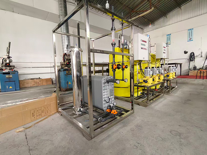
Yuan LaiEDIThe ultra-pure water equipment uses electro-deionization technology.EDIElectrodeionization is a water purification method that combines the dual advantages of electrodialysis and ion exchange. It does not require acid-base chemical regeneration and can continuously and stably prepare high-purity ultrapure water. Under the action of a direct current electric field, ion separation in water is completed. At the same time, water is electrolyzed to generate hydrogen ions and hydroxide ions, achieving automatic regeneration of the resin without the need to stop the machine for manual regeneration. The pre-treatment combined with reverse osmosis can prevent oxidized substances from damaging the resin, ensuring stable effluent quality and widely meeting the high-standard water usage requirements of various industries.
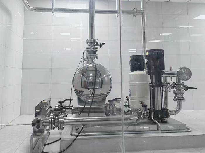
The non-negative pressure water supply equipment can be directly connected to the municipal water supply network, making full use of the residual pressure of the original network for superimposed water supply. Fully enclosed operation does not require the construction of a domestic water tank, eliminating secondary pollution. Intelligent variable frequency voltage stabilization, energy-saving, quiet and easy installation, it is the preferred equipment for secondary water supply in high-rise residential buildings and commercial buildings.
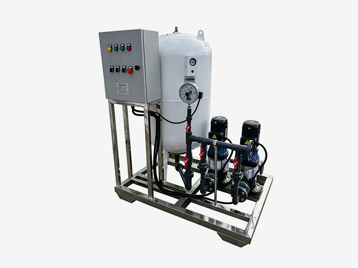
Constant pressure water supply equipment is widely used in central air conditioning, floor heating, industrial closed-loop water circulation, and boiler systems. It integrates automatic pressure stabilization, automatic water replenishment, automatic exhaust, pressure relief and buffering functions. It stabilizes the pressure in the pipeline network, eliminates abnormal sounds caused by air blockage, and prevents damage from negative pressure and water shortage in the pipeline. It is an essential supporting equipment for HVAC and circulating water systems.













 Landline:+86 010 59792055
Landline:+86 010 63780188
 Mobile:+86 13910114728
 Email:bjyuanlai@163.com
 Email:Wanda Plaza, Fengke Road, Fengtai District, BeijingBseat6Courtyard No.3Building No.7layer708
Yuanlai Homepage Softened water equipment Reverse osmosis pure water equipment Water supply equipment Engineering case Technical service Enter Yuanlai Site map
Softened water equipment Reverse osmosis pure water equipment Water purification equipment Water supply equipment Automatic dosing equipment High-purity water (ultra-pure water) equipment Wholesale of water treatment accessories
Electric power industry Petrochemical industry The electronic semiconductor industry The photovoltaic new energy industry Pharmaceuticals & Biochemical Engineering School research units Food and beverage industry Enterprises and public institutions
Reverse osmosis membrane Star-counting pump Fleck Valve Runxin Valve Instruments and meters Ultrafiltration membrane Softening resin Resin tank
