Bookmark this site Online message 中文站Welcome to the official website of Beijing Yuanlai Water Treatment Equipment Co., LTD.!
Service Hotline
+86 010 59792055 / +86 13910114728

Water treatment of boilers is an important measure to ensure their economic operation. Improper water treatment can lead to the formation of scale on the heating surface. This not only reduces the heat transfer efficiency but, in severe cases, can also clog the heating surface tubes, causing boiler tube burst accidents. The water quality is poor, especiallypHWater with a low oxygen content and high oxygen content can cause corrosion to the metal of boilers, leading to pipe leakage and even boiler explosions.Now let's talk about how to install and debug the boiler water treatment equipment.
Boiler water treatment should be able to ensure that the water quality of the boiler meets the requirementsGB1576The provisions of the "Water Quality for Low-Pressure Boilers" standard or the "Water and Steam Quality for Thermal Power Generating Units and Steam Power Equipment" standard.
Water treatment methods are generally classified asThe treatment of adding chemicals in the pot and the treatment of water outside the pot.
1 Add medicine to the pot for treatment
Adding chemicals to the pot is relatively simple. You can use a water injector, a water tank or a pressure dosing method.
2 Water treatment outside the pot
The treatment of water outside the pot usually adopts the ion exchange method, and a sodium ion exchanger is generally used.
2.1 Acceptance and inventory of equipment and materials
2.1.1 All equipment, components and materials entering the site should be counted and visually inspected. Records of the count and acceptance should be kept. Any defects found should be reported to the company's quality assurance personnel, who will then declare and handle them.
2.1.2 The unpacking inspection of the equipment should be carried out with the participation of relevant personnel from the construction unit, and the following records should be made:
(1Box number, quantity of boxes and packaging conditions;(2Equipment name, specification, model;
(3Packing list, technical documents, materials and special tools;(4Check if there are any missing parts on the equipment, and if there is any damage or rust on the surface.
2.1.3Metal nameplates shall be installed in prominent positions, and the following items shall be indicated on the nameplates:
(1)Equipment model;(2)Manufacturer's name, equipment product number; (3)Manufacturing License number (4)Manufacturing date.
2.1.4Check whether the outer shell of the equipment cylinder is deformed or cracked. Check whether the pipes at the water inlet, water outlet, sewage outlet, etc. are bent or deformed, and whether the flanges have cracks, damage or deformation.
2.1.5All materials should have a certificate of conformity. When there is doubt about the quality during verification, necessary inspection and appraisal should be carried out.
2.1.6Pipe inspection
(1The surface of the pipe should be smooth, free from defects such as cracks, slag inclusions, double skins, and severe rust.
(2The wall thickness of the pipe should not exceed the negative deviation. If there are local defects such as scratches, pockmarks, pits or corrosion on its surface, their depth should not exceed the nominal wall thickness of the pipe10%
(3The pipe shall be accompanied by a certificate of conformity issued by the manufacturer, which shall indicate:
①Name and code of the manufacturer and supplier;②Contract number and steel grade;③Product name and specification model;
④Standard number;⑤Chemical composition;⑥Test results;⑦Furnace number, batch number, weight.
2.1.7Valve inspection
(1The specifications, models, materials and technical parameters of the valves shall comply with the design requirements.
(2The packing of each valve should be inspected one by one
(3Low-pressure valve (working pressure≤2.5MPaIt should be no less than each batch10%Conduct strength and tightness tests in proportion. If any one of them is unqualified, it must be pressed separately20%Double the spot checks. If there are still any non-conformities, they should be inspected one by one.
The valve strength test should be conducted in accordance with1.5The test is conducted at times the nominal pressure for a period of5minIt is qualified when there is no leakage in the shell and packing.
The valve tightness test should be conducted in accordance with1.25The test is conducted at times the nominal pressure for a period of10minThe valve disc is qualified if there is no leakage at the sealing surface.
2.2 Basic inspection and marking
2.2.1Basic check
(1)The quality of the equipment foundation should comply with the design requirements and current national standards, and there should be acceptance documents or records. The basic surface should be free of defects such as cracks, honeycombs, exposed ribs and missing corners.
(2)According to the layout plan of the boiler room and the basic data of the civil construction, check the planar position of the equipment foundation. Use a steel tape measure to check the longitudinal and transverse reference lines of all equipment foundations. The relative coordinate position deviation should not exceed±20mm.
(3) According to the equipment foundation drawing and the civil engineering elevation reference line, check the elevation of the equipment foundation. Use a glass tube level or a level to check the elevations of different planes of the foundation. The elevation difference should not exceed0------20mm.
(4)When the quality and dimensions of the foundation do not meet the requirements, the construction unit should jointly propose handling opinions and carry out handling to meet the requirements.
(5)Oil stains, crushed stones, soil, accumulated water, etc. on the surface of the equipment foundation and the reserved holes of the anchor bolts should all be cleaned up thoroughly. The threads and nuts of the embedded anchor bolts should be well protected. The surface where the shims are placed should be chiseled flat.
(6)After the acceptance is qualified, the test results should be filled in the construction record form respectively. After being signed by both Party A and Party B, the supervision and inspection institution should be notified.
2.2.2 Basic line drawing
According to the construction drawings and the axes or edge lines of relevant buildings, the longitudinal and transverse reference lines for equipment installation should be marked out. For equipment with an arrangement relationship, a common installation reference line should be delineated.
2.3The equipment is in place and aligned
(1)Use a forklift or tow to transport the water treatment equipment(Ion exchanger) Transport it to the foundation, hoist it onto the equipment foundation, and use a plumb line hammer and a steel tape measure to align its coordinate position and verticality with the cylinder as the reference.
(2)Anchor bolts are embedded
(3)The anchor bolts should be vertical and not tilted in the reserved holes.
(4)The distance between any part of the anchor bolt and the hole wall should≥15mmThe bottom end of the anchor bolts should not touch the bottom of the hole.
(5)The oil stains and oxide scale on the anchor bolts should be cleaned thoroughly, and a small amount of grease should be applied to the outside of the threads.
(6)The contact between the nut, washer and the equipment base should all be tight.
2.3.3Iron pad placement
(1)The shims used for equipment alignment should comply with the requirements of the equipment technical documents.
(2)There should be at least one set of shims beside each anchor bolt, and the position of the shims should be close to the main force-bearing parts of the anchor bolt and the base.
(3)The distance between two adjacent shims groups should≤1000mm.
(4)Each group of shims should not exceed5The blocks should be made and the rear shims should be welded firmly to each other with positioning welding.
(5)Each shims assembly should be placed neatly and stably with good contact. The end face of the shims should expose the outer edge of the bottom surface of the equipment10~30mm.
2.3.4Grouting
(1)After the water treatment equipment is aligned, secondary grouting can be carried out. The secondary grouting work is generally conducted by civil construction. If it is carried out by oneself, it should comply with the design requirements and the current national standard "Code for Construction and Acceptance of Reinforced Concrete Works".
(2)Before grouting, the grouting area should be thoroughly cleaned. Fine crushed stone concrete is generally used for grouting, and its strength should be one grade higher than that of the foundation concrete. When grouting, it should be compacted and the anchor bolts should not be tilted or affect the installation accuracy of the equipment. The thickness of the grouting layer should not be less than25mm.
2.4 Installation of accessories
Install the equipment connectors, pipe fittings and valves in accordance with the design drawings and random documents. Do not force them together. When installing operating components such as valves, convenience of operation should be taken into consideration.
2.5 Installation of the regeneration system
The main regenerants used in ion exchangers are solid salts and liquid acids and bases. The salt system is mainly used for water softening, while the acid-base system is mainly used for chemical desalination or hydrogen ion exchange.
2.5.1Salt systems are divided into pressure type and gravity type
(1)The pressure type salt dissolver serves two functions: dissolving salt and filtering brine. Its working pressure≤0.1MPaThe filtration speed is usually within5m/hThe specifications are φ300mm, φ500mm,φ750mm,φ1000mm.
(2)The installation of a pressure-type salt dissolver is basically the same as that of an ion exchanger.
(3)Gravity salt systems generally have salt dissolving tanks(box) And a salt transfer pump
2.5.2Salt dissolving tank(box) And install the salt transfer pump
The salt dissolving tank is made of concrete and the salt dissolving box is made of steel plates(Inner lining plastic board) There is a partition in the middle to hold the salt pool2/5and3/5The volume ratio is divided into two parts, with many openings on the partitionφ10mmThe hole. Add salt and water3/5On one side of the volume, the salt dissolves and flows through the holes on the partition2/5One side of the volume. Then, use a salt water pump to pass it through the filter and add it to the ion exchanger.
The installation of the water treatment equipment has been completed and the acceptance procedures have been handled.
3 Debugging
3.1 Debugging preparation
(1)The water treatment equipment and auxiliary equipment have been installed and accepted as qualified.
(2)Prepare a sufficient quantity of exchangers that meet the requirements as stipulated in the equipment technical documents(Ion exchange resin)And salt(Industrial salt) .
(3)According to the requirements of the equipment technical documents, add the exchanger to the exchanger, add salt to the pressure salt filter or salt dissolving tank, and add water to dissolve it.
3.2 The operation of a sodium ion exchanger is generally divided into four steps:①Backwashing②Regeneration;③"Forward washing;"④Run.
(1)Backwashing: Use water at a certain pressure to strongly backwash the resin layer from bottom to top for a short period of time. The purpose is to wash away the suspended solids, particles and bubbles on the surface of the exchanger and loosen the exchanger layer.
(2)Regeneration: Dynamic regeneration should be adopted during regeneration, that is, the regenerant should be introduced at the beginning(The concentration of the salt solution is6~10×10-2"Appropriate) While doing so, open the drain valve and drain the regenerant simultaneously. When operating, the opening degree of the drain valve should be strictly controlled to ensure that the flow rate of the regenerant is constant3~5m/hAnd ensure that all exchange layers are immersed in the regenerant, with a regeneration time of no less than40min.
(3)Forward washing: The purpose of forward washing is to clean the residual regenerant and products in the exchanger(CaCl2,MgCl2) . The initial flow rate for forward washing should not be too high and can be controlled within3~5m/h; When the water from the forward wash is basically not salty, the flow rate can be increased to10~15m/h; In the later stage of forward washing, samples should be taken frequently to test the hardness of the effluent. When the water hardness meets the standard and the chloride content does not exceed the chloride ions in the raw water50~100mg/LAt that time, it can be put into exchange operation.
(4)Exchange operation: During the sodium ion exchange softening process, the exchanger is divided into three layers. The first layer is the failure layer, the second layer is the working layer, and the third layer is the protective layer. During the exchange process, the layers gradually increase in size, the layers gradually move downward, and the third layer gradually shrinks until the lower edge of the layer moves to coincide with the lower edge of the exchanger layer, at which point the exchanger begins to fail.
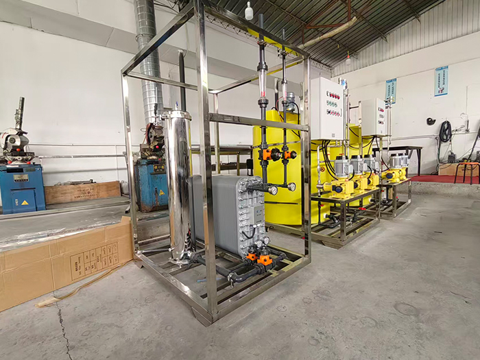
Yuan LaiEDIThe ultra-pure water equipment uses electro-deionization technology.EDIElectrodeionization is a water purification method that combines the dual advantages of electrodialysis and ion exchange. It does not require acid-base chemical regeneration and can continuously and stably prepare high-purity ultrapure water. Under the action of a direct current electric field, ion separation in water is completed. At the same time, water is electrolyzed to generate hydrogen ions and hydroxide ions, achieving automatic regeneration of the resin without the need to stop the machine for manual regeneration. The pre-treatment combined with reverse osmosis can prevent oxidized substances from damaging the resin, ensuring stable effluent quality and widely meeting the high-standard water usage requirements of various industries.
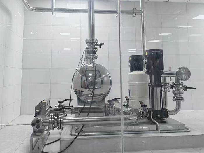
The non-negative pressure water supply equipment can be directly connected to the municipal water supply network, making full use of the residual pressure of the original network for superimposed water supply. Fully enclosed operation does not require the construction of a domestic water tank, eliminating secondary pollution. Intelligent variable frequency voltage stabilization, energy-saving, quiet and easy installation, it is the preferred equipment for secondary water supply in high-rise residential buildings and commercial buildings.
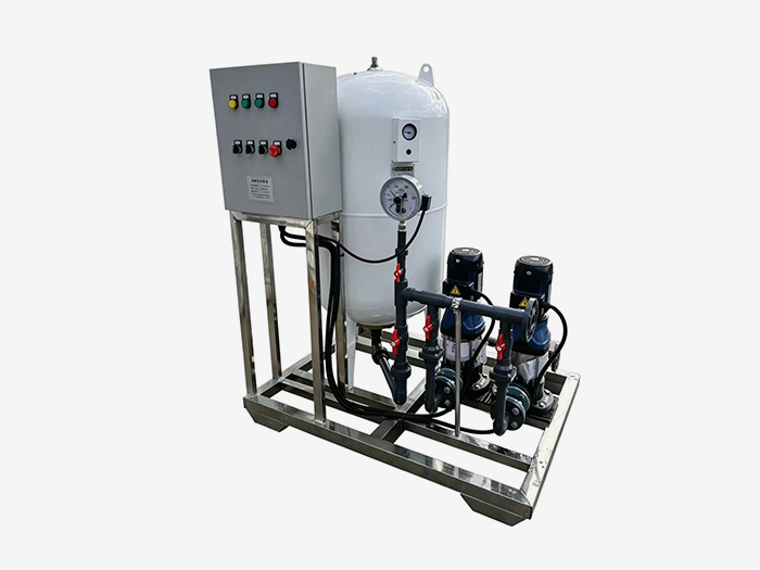
Constant pressure water supply equipment is widely used in central air conditioning, floor heating, industrial closed-loop water circulation, and boiler systems. It integrates automatic pressure stabilization, automatic water replenishment, automatic exhaust, pressure relief and buffering functions. It stabilizes the pressure in the pipeline network, eliminates abnormal sounds caused by air blockage, and prevents damage from negative pressure and water shortage in the pipeline. It is an essential supporting equipment for HVAC and circulating water systems.











 Landline:+86 010 59792055
Landline:+86 010 63780188
 Mobile:+86 13910114728
 Email:bjyuanlai@163.com
 Email:Wanda Plaza, Fengke Road, Fengtai District, BeijingBseat6Courtyard No.3Building No.7layer708
Yuanlai Homepage Softened water equipment Reverse osmosis pure water equipment Water supply equipment Engineering case Technical service Enter Yuanlai Site map
Softened water equipment Reverse osmosis pure water equipment Water purification equipment Water supply equipment Automatic dosing equipment High-purity water (ultra-pure water) equipment Wholesale of water treatment accessories
Electric power industry Petrochemical industry The electronic semiconductor industry The photovoltaic new energy industry Pharmaceuticals & Biochemical Engineering School research units Food and beverage industry Enterprises and public institutions
Reverse osmosis membrane Star-counting pump Fleck Valve Runxin Valve Instruments and meters Ultrafiltration membrane Softening resin Resin tank
