Bookmark this site Online message 中文站Welcome to the official website of Beijing Yuanlai Water Treatment Equipment Co., LTD.!
Service Hotline
+86 010 59792055 / +86 13910114728


I. Basic environments and conditions suitable for this type of equipment
Inlet pressure of tap water0.2MPa-0.6MPa
Operating temperature2℃-50℃
Raw water hardness≤10mmol/L
Soft water hardness≤0.03mmol/L
Power supply used:220V/50HZ
Regeneration method: Mainly co-current regeneration(Some models are regenerated against the current)
The layout form of the process system: single-tank softening or parallel connection of softeners for two or more tanks
Resin model001×7Strongly acidic styrene-based cation exchange resin.
Ii. Installation and Startup of the water Softener
1The water softener should be installed on a solid and level ground. The distance from the drainage ditch should be as short as possible, and the distance from heat sources such as boilers should be greater than3Rice, keep away from acidic liquids or gases. If other water treatment equipment (such as filters, deaerators, etc.) needs to be added, space should be reserved.
2The regeneration salt tank should be placed as close as possible to the resin tank. To make full use of the salt solution, the length of the plastic pipe for absorbing the salt solution should be shortened as much as possible.
3Before filling the resin, place the lifting pipe at the bottom of the resin tank (align the bottom end of the water distribution cap with the bottom of the resin tank).
4Remove the protective tape from the lifting pipe, align the upper end of the lifting pipe with the connection port at the bottom of the control valve, and carefully rotate the control valve clockwise. (Remember that during the installation of the control valve, make sure the lifting pipe is inserted into the valve body and kept concentric, and the control valve is firmly fastened to the tank.)
5Connect the pipes and power supply according to the installation diagram. All inlet and outlet pipelines have independent supports and cannot be supported by valve bodies. When starting the water softener, the bypass valve should be closed and then the outlet should be opened
Open the inlet control valve first, then slowly open the inlet control valve (remember not to open the inlet control valve too quickly, as this may cause water and residual air in the pipeline to enter the water softener and cause the resin to run out of the tank along with the water flow.)
6Set the time and program controller according to the method described in this manual. The initial operation is divided into stages. Strengthen the monitoring of the effluent quality and adjust the restoration program according to the changes in water quality to achieve the best treatment condition.
7There should always be sufficient solid regenerant in the salt tank to maintain saturated brine and ensure the amount of salt used in each regeneration cycle.
8The drainage pipe installation system should not install any valves. The shorter the pipe, the better, and the fewer the elbows, the better. The total length should be less than6The drainage pipes should not be raised, and the siphoning phenomenon of the drainage pipes should be prevented.
9The issue of adjusting water sources with fluctuating water quality and pressure.
Due to the significant variations in water hardness and pressure in some regions of our country, when users use flow-type or time-type Flike equipment, the pre-set programs will be affected or lead to premature regeneration, resulting in the waste of regenerant, or delayed regeneration, which cannot guarantee the quality of soft water. The occurrence of these two problems will bring corresponding hazards to the economic operation of boilers and other pressure vessel equipment.
10Note:
(1Users can install water meters at the soft water outlet as needed
(2If the water pressure is unstable, users should install pressure gauges at the inlet and outlet
(3There should be a sewage floor drain on the working ground
(4In areas with poor water quality, filters and exhaust valves should be installed at the water inlet
(5The pipeline should be supported by force to prevent force from acting on the control valve and damaging it
(6For backup purposes, the inlet and outlet water pipelines can be directly connected by adding shutters
(7"Needed"220VPower supply
Iii. Control System Water Treatment Process Flow
Preparation of soft waterSERVICE POSITIONHard water passes through the control valve and flows downward through the resin layer to achieve softening. Then, it moves upward through the bottom diverter of the lifting pipe and is discharged through the outlet of the control valve as softened water.
BackwashingBACKWASH POSITIONHard water enters the control valve and flows downward through the lift pipe. The bottom distributor distributes it to the exchanger layer. After backwashing and exchanging from bottom to top, the wastewater is discharged through the drain port of the control valve.
RegenerationBRINE POSITIONHard water enters the control valve and then ascends into the water injector. Subsequently, through the jet process, the regeneration and reduction agent in the salt tank is drawn into the brine by the siphon principle and evenly distributed from top to bottom in the exchanger layer for regeneration and reduction. The waste liquid moves downward through the bottom diverter of the lifting pipe and is discharged through the drain port of the control valve.
Slow cleaning (i.e. displacement or small cleaning)SLOW RINSE POSITIONHard water enters the resin tank through the control valve and flows evenly from top to bottom through the resin layer. Then, it passes through the bottom diverter of the lifting pipe and moves from bottom to top along the pipe. Finally, the waste liquid is discharged through the outlet of the control valve.
Quick cleaning (big cleaning)PAPID RINSEHard water enters the resin through the control valve, rapidly washes the exchanger layer from top to bottom, and then flows in from the bottom of the lifting pipe. After moving along the pipe, it is discharged through the outlet of the control valve.
Fill the salt tank with water to prepare the salt solutionBRINE TANK FILL POSITIONHard water enters the control valve to supply water to the resin tank. At the same time, it flows through the water injector into the brine valve to fill the brine tank with water, dissolving sodium chloride to produce saturated brine.
Iv. Explanation of Relevant Issues regarding Time-controlled Regenerative Type
1How to set the regeneration date:
Turn the date wheel to make the digital"1Align with the red arrow on the date wheel. Each small protrusion on the edge of the date wheel represents a day. The rotation of the date wheel relies on24The drive of the hour clock. When the time disk rotates once, a protrusion is played. A stainless steel plate can be pulled out from the date wheel to determine the regeneration date. The day when the stainless steel sheet corresponding to the number is pulled out is the regeneration date.
2How to set the time
Press the red button and release it24The meshing of the hour dial, rotate the time dial until"time of dayAlign the arrow with the real time of the day, release the button and resume engagement with the time dial.
3How to regenerate manually
Turn the manual regeneration knob clockwise. When you hear a "click" sound, it indicates that the regeneration process has begun. Turning the manual regeneration knob once is approximately the right time3In hours, one rotation completes one regeneration process.
4How to set the regeneration cycle program:
The regeneration cycle program has been set at the time of production3It takes hours, but the regeneration process time can be extended or shortened according to the local water quality conditions of the user. Unscrew the black nut on the upper left of the time dial, and then turn the timer to the right to see the regeneration timer. To change the regeneration program, remove the timer. The method is to unscrew the nut in the middle of the timer and pull it outward. Then the timer will be removed from behind the timer.
5How to change the length of backwashing time
A number is marked on the edge of the timer.0-160), from0The initial group pin is used to control the backwashing time. For example, if each group has six pins, the backwashing time is12Minutes (One pin is.2Changing the number of pins in minutes accordingly alters the backwashing time
Between.
6How to change the duration of salt absorption, water injection and slow washing
The number of pin holes between the pins of the timer group is the time for controlling these two states, and each hole is equivalent to2In minutes, the number of holes can be increased or decreased to change the length of the brine absorption and slow washing time. When adjusting, the position of the group pin can be moved to increase or decrease the number of holes.
7How to change the length of the quick wash time
The number of group pins on the timer controls the length of the quick wash time. For each additional or reduced pin, increase or decrease the quick wash by two minutes.
8How to change the duration of filling the salt tank with water
The number of group pin holes on the timer is used to control the duration of water injection. Each hole is equivalent to2In minutes, when adjusting, increase or decrease the number of holes by moving the position of the third group of pins.
The regeneration program terminates when an external microswitch comes into contact with the two pins at the end of the water injection pin hole. However, the timer will continue to rotate until a microswitch contact arm on the straight surface is turned into the circular notch of the timer.
Note: The brine tank is always replenished with water at any time, so the salt volume in the tank should meet the requirements of the next regeneration process.
V. Explanation of Relevant Issues Regarding Flow Control Regeneration Type
1The setting of traffic flow
The set flow rate is calculated by subtracting the necessary reserve volume from the periodic water production volume based on the exchange capacity of the resin filled in the resin tank. Pull out the flowmeter and rotate it to align the set flow rate with the white dot on the flowmeter. Then release the flowmeter and make sure the gears mesh well.
Note: After the initial installation of the flowmeter, an inspection should be carried out
①Turn the manual regeneration valve and go through the procedure once
②Turn the program wheel clockwise or rotate the wheel clockwise to align the set flow rate with the white point
③The set traffic can be changed at any time
2Time setting
①Press the red button and release it24The meshing of the hour dial
②Turn the time disk to align the actual time of the day with the words"time fo dayThe arrow of ".
③Release the red button to reengage with the time dial
3How to regenerate manually
①Turn the manual regeneration knob clockwise and you will hear a "click" sound, which indicates that the regeneration process has begun
②The manual regeneration knob is approximately timed when turned once3In hours, one full turn of the knob completes one regeneration process
4Start regeneration immediately
When the flow disk rotates to the number you have set, the timer starts to regenerate.
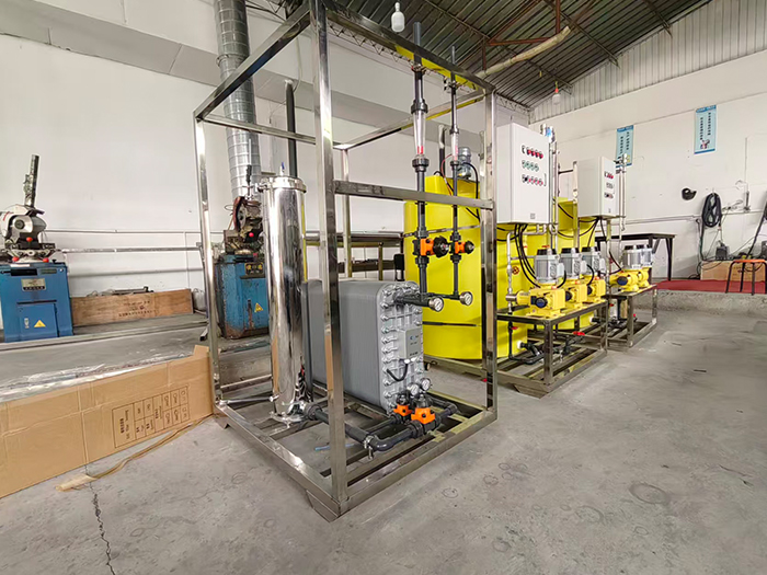
Yuan LaiEDIThe ultra-pure water equipment uses electro-deionization technology.EDIElectrodeionization is a water purification method that combines the dual advantages of electrodialysis and ion exchange. It does not require acid-base chemical regeneration and can continuously and stably prepare high-purity ultrapure water. Under the action of a direct current electric field, ion separation in water is completed. At the same time, water is electrolyzed to generate hydrogen ions and hydroxide ions, achieving automatic regeneration of the resin without the need to stop the machine for manual regeneration. The pre-treatment combined with reverse osmosis can prevent oxidized substances from damaging the resin, ensuring stable effluent quality and widely meeting the high-standard water usage requirements of various industries.
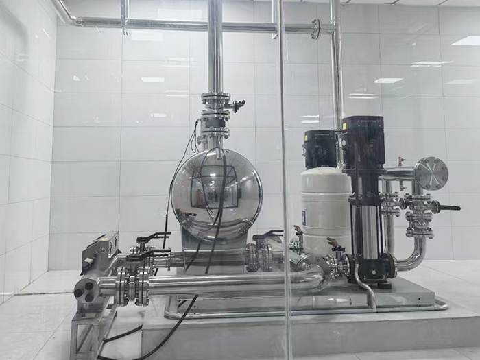
The non-negative pressure water supply equipment can be directly connected to the municipal water supply network, making full use of the residual pressure of the original network for superimposed water supply. Fully enclosed operation does not require the construction of a domestic water tank, eliminating secondary pollution. Intelligent variable frequency voltage stabilization, energy-saving, quiet and easy installation, it is the preferred equipment for secondary water supply in high-rise residential buildings and commercial buildings.
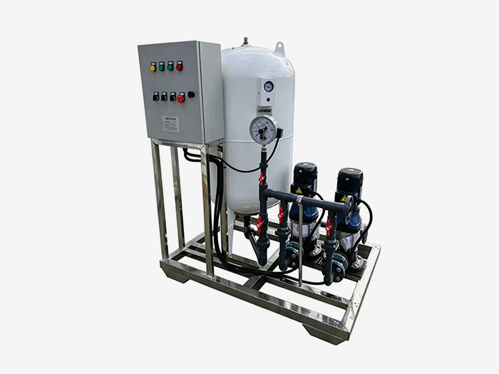
Constant pressure water supply equipment is widely used in central air conditioning, floor heating, industrial closed-loop water circulation, and boiler systems. It integrates automatic pressure stabilization, automatic water replenishment, automatic exhaust, pressure relief and buffering functions. It stabilizes the pressure in the pipeline network, eliminates abnormal sounds caused by air blockage, and prevents damage from negative pressure and water shortage in the pipeline. It is an essential supporting equipment for HVAC and circulating water systems.












 Landline:+86 010 59792055
Landline:+86 010 63780188
 Mobile:+86 13910114728
 Email:bjyuanlai@163.com
 Email:Wanda Plaza, Fengke Road, Fengtai District, BeijingBseat6Courtyard No.3Building No.7layer708
Yuanlai Homepage Softened water equipment Reverse osmosis pure water equipment Water supply equipment Engineering case Technical service Enter Yuanlai Site map
Softened water equipment Reverse osmosis pure water equipment Water purification equipment Water supply equipment Automatic dosing equipment High-purity water (ultra-pure water) equipment Wholesale of water treatment accessories
Electric power industry Petrochemical industry The electronic semiconductor industry The photovoltaic new energy industry Pharmaceuticals & Biochemical Engineering School research units Food and beverage industry Enterprises and public institutions
Reverse osmosis membrane Star-counting pump Fleck Valve Runxin Valve Instruments and meters Ultrafiltration membrane Softening resin Resin tank
